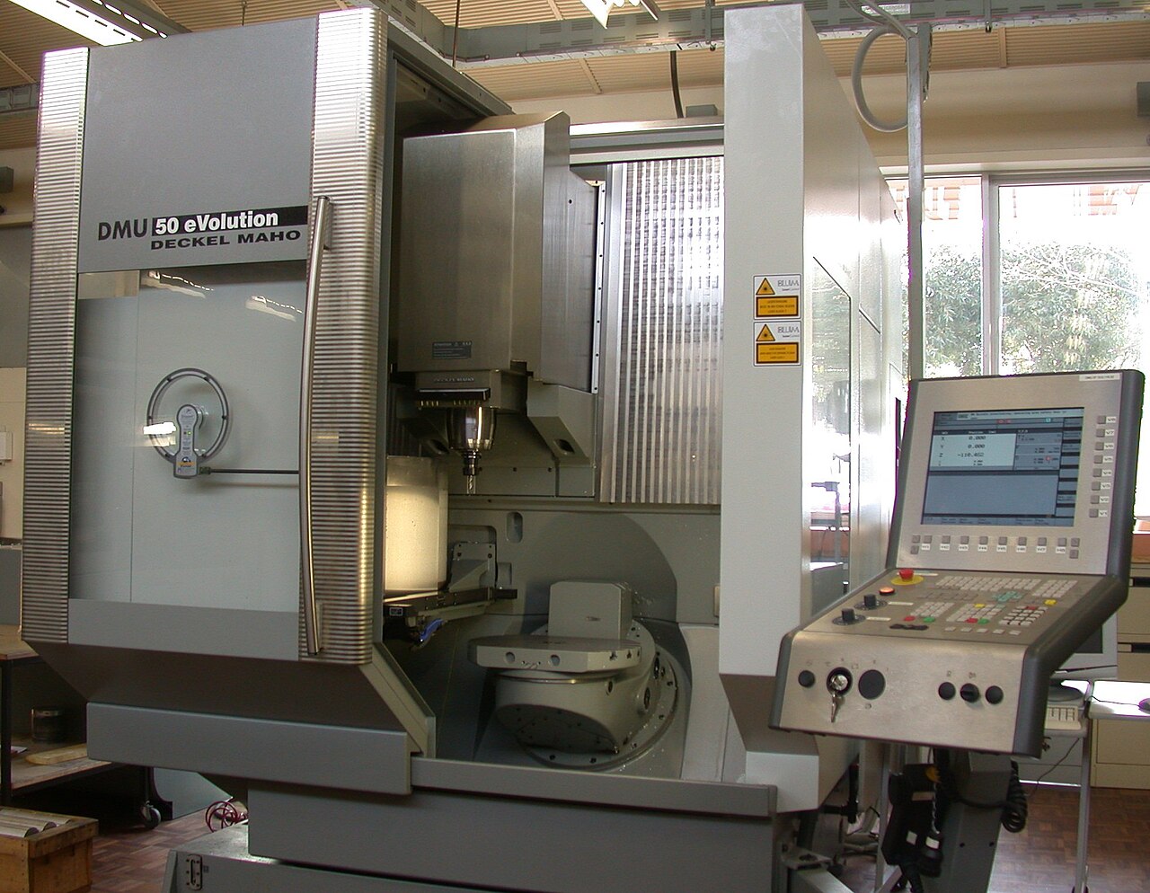
Custom precision forgings from 0.1 to 500 kg, tolerances to ±0.2 mm, delivered in 30 days. Six material classes — carbon steel, alloy steel, stainless steel, aluminum, titanium and nickel alloys — with die design, hot forging, heat treatment, CNC machining and NDT under one roof.
Safety-rated forged components for passenger cars and commercial trucks, meeting industry standards.
Steering knuckles, control arms, tie rod ends — safety-rated forged components.
Connecting rods, gear blanks, flanges, transmission parts requiring high fatigue strength.
Axle beams, spring hangers, chassis brackets for heavy-duty applications.
High-strength forgings for airframes, engines, and landing gear with full documentation package.
Bulkheads, ribs, frames, and wing attachment fittings in aluminum and titanium alloys.
Turbine discs, compressor blades, engine mounts, and casings in nickel alloys and titanium.
Landing gear beams, torque links, and actuator components meeting military specifications.
Pipe flanges, bearing rings, gear blanks for oil & gas, power generation, and heavy machinery.
Step shafts, drive shafts, pinions for transmission systems and industrial gearboxes.
Housings, brackets, levers, and bespoke parts per customer drawing.
| Parameter | Range |
|---|---|
| Materials | Carbon steel, alloy steel, stainless, aluminum, titanium, nickel alloys |
| Part Weight | 0.1 kg – 500 kg |
| Tolerance | ±0.2 mm on critical dimensions |
| Batch Volume | 10 (prototype) – 100,000+ (mass production) |
| Lead Time | 4-8 weeks (first order, tooling incl.), 3-5 weeks (repeat) |
A ForgePress China forging ships as a finished, dimensionally verified component, not as a rough blank. Five processes run in-house — die design, hot die forging on the HKM3 line from 1,000 to 5,000 t, heat treatment, CNC machining and non-destructive testing — so the part that leaves the plant has already passed the inspection the drawing asks for. Weight range is 0.1–500 kg, machined critical dimensions hold ±0.2 mm, as-forged surfaces follow ISO 8062 class C, unmachined general tolerances follow ISO 2768-m, and the quality system is ISO 9001. First articles take 4–8 weeks from die design release; repeat orders run 3–5 weeks.
Six families cover most of what leaves the plant. For each one the table names the part types, the weight band they usually fall in, the materials that are actually used, and the one characteristic that decides whether the lot passes.
| Family | Typical parts | Usual weight | Materials | What decides acceptance |
|---|---|---|---|---|
| Steering & suspension | Knuckles, control arms, tie-rod ends, ball-joint housings | 1.5–25 kg | Carbon steel, alloy steel (42CrMo4) | Fatigue life at the fillet; grain flow must follow the arm, not cross it |
| Powertrain | Connecting rods, gear blanks, flanges, input/output shafts | 0.5–20 kg | Alloy steel (42CrMo4, 20CrMnTi) | Weight tolerance per rod and the balance spread across a set |
| Chassis & frame | Axle beams, spring hangers, brackets, suspension mounts | 5–120 kg | Carbon steel, alloy steel | Straightness after heat treatment, and hole position relative to the beam centreline |
| Flanges & rings | Weld-neck and slip-on flanges, bearing rings, gear ring blanks | 2–80 kg | Carbon steel, stainless (304/316) | Concentricity of bore to face; seal-groove finish after machining |
| Shafts & axles | Step shafts, drive shafts, pinions, stub axles | 1–60 kg | Alloy steel, carbon steel | Runout over the full length, not just at the journals |
| Housings & brackets | Gearbox housings, bearing caps, levers, bespoke parts to drawing | 0.1–500 kg | All six classes | Wall-thickness variation, and whether the datum survives draft on the as-forged surface |
The weight column is what these families usually weigh, not a limit. The limit is 0.1–500 kg and a maximum die envelope of 1,200 × 800 mm.
Six classes are quoted. Naming the class is not enough — the grade inside the class decides heat treatment, die life and price. Grade availability is confirmed at RFQ; not every grade in a class is held in stock.
| Class | Common grades | Why you would choose it | What to watch |
|---|---|---|---|
| Carbon steel | C45 / 1045, C22 / 1020 | Cheapest path to a strong, machinable part when corrosion is not a factor | Through-hardening depth is limited; do not specify it for sections over roughly 50 mm |
| Alloy steel | 42CrMo4 / 4140, 40Cr, 20CrMnTi / 8620 | Hardenability and fatigue strength for rods, shafts and gears | 20CrMnTi and 8620 are not interchangeable; the case depth and core hardness differ |
| Stainless steel | 304, 316, 17-4PH | Corrosion resistance without a coating; 17-4PH when you also need strength | Hot forging window is narrow and scale is heavier; machining stock has to be planned for it |
| Aluminum | 6061, 6082, 7075 | Weight reduction on brackets and housings | Draft and shrink behave differently from steel; die layout is not transferable between the two |
| Titanium | Ti-6Al-4V | Strength-to-weight where aluminum is not enough and temperature rules out polymer | Narrow forging window and high die wear; cost per kg is driven by die life, not by the billet |
| Nickel alloys | Inconel 718 and equivalents | Retains strength at elevated temperature | Highest die wear of the six; expect a different die material and a shorter die life than steel work |
Material is verified on receipt by optical emission, so a certificate that says 42CrMo4 and a billet that is not 42CrMo4 do not get to become your part.
Most tolerance arguments come from one ambiguity: whether a dimension is met on the as-forged surface or after machining. These are different processes with different capabilities, and the ±0.2 mm figure belongs to the second one only.
| Feature | As forged | After machining | How it is checked |
|---|---|---|---|
| Overall length and width | ISO 8062 class C on the as-forged surface | Drawn dimension, ±0.2 mm on critical features | CMM, full dimensional report |
| Thickness across the parting line | Class C plus flash-line allowance | Ground or milled flat if the drawing calls it critical | Micrometer at four points per lot |
| Holes and bores | Not forged to final size — cored under-size | Bored or reamed to drawing | Bore gauge and CMM |
| Draft on as-forged walls | Required for release, typically 3–7° per side | Removed by machining where the drawing is vertical | Angle gauge on first article |
| Fillet radii | Forged, not machined | Held to the die, not to a tolerance band | Profile projector or radius gauge |
| General tolerances not shown on the drawing | ISO 8062 class C governs forging | ISO 2768-m governs machined features | Per the drawing callout |
Draft is the one that catches people out: a face that is vertical on the drawing is not vertical as forged, so it cannot be a datum until it has been machined. If a datum sits on a drafted face, the inspection plan has to say so before the die is cut.
Quotes on the same drawing can differ by far more than a supplier margin. When they do, it is usually one of these five, and each is something the buyer controls.
Material is bought by weight and the press is chosen by envelope. A part that fits a 1,000 t line and one that needs 5,000 t are not in the same cost band even at equal weight.
Every thousand shots is amortised into the piece price. A shape that wears the die faster costs more per part than a heavier part that does not.
Closed-die work with a sensible flash allowance wastes less billet. Yield, not the billet price, is usually the larger lever.
As-forged surfaces must be cut away wherever the drawing is precise. Extra stock is extra time on the machine.
A dimensional report, a material certificate and UT/MT each add cost. Specify what the part actually needs — over-specifying inspection is a common and quiet overspend.
The 4–8 week first-article figure is a sum of blocks, not a guess. Knowing which block you are in is the difference between a realistic launch date and an optimistic one.
| When | Stage | What happens |
|---|---|---|
| Week 0 | RFQ and quote | Send drawing plus material, annual volume and inspection requirement. A quote returns within 24 hours. |
| Week 0–1 | DFM review and die layout | We return a die layout with parting line, draft, shrink and machining stock marked. Nothing is cut before you approve it. |
| Week 1–4 | Die build | Die blocks are ordered, sunk, heat treated and the cavity is spotted in. This is the longest block, and it is why first articles are not a two-week item. |
| Week 4–5 | First article | Parts are forged, heat treated, machined and inspected. You receive a dimensional report, material certificate and NDT result before the run continues. |
| Week 5–8 | Production and shipment | Batch runs to the approved setting sheet, final inspection per the agreed plan, packing to your marking requirement. |
| Repeat orders | 3–5 weeks | Die is already proven, so the die-build block drops out and only forging, heat treatment, machining and inspection remain. |
The week numbers are the typical band for a two-cavity die and are confirmed at die layout approval. A simple single-cavity part lands nearer the 4-week end; a part that needs simulation iteration lands nearer the 8.
Eight items. Sending all eight is what makes a 24-hour quote possible; missing three of them is what turns a quote into a week of email.
Request a quotation → or email drawings to wuq268022@gmail.com
The same five questions published in this page's structured data — one source, so the visible answer and the machine-readable answer cannot drift apart.
0.1 kg to 500 kg per finished forging, across six material classes: carbon steel, alloy steel, stainless steel, aluminum, titanium, and nickel alloys.
Down to +/-0.2 mm on machined critical dimensions. As-forged stock is removed by in-house CNC, which is why the final tolerance is held under one roof instead of being split across suppliers.
30 days from drawing approval for repeat parts. First articles take 4-8 weeks because die design, simulation, and first-article inspection come first.
Finished parts. Heat treatment, CNC machining, and NDT run in-house, so parts ship as dimensionally verified components rather than raw forgings.
24 hours after you send a drawing in STEP, IGES, DWG, or PDF format, together with material specification and annual volume.
This page answers what we make. The four capability pages answer how each step is controlled.
Parting line, draft, shrink, tonnage calculation and die layout approval — what has to be settled before a die block is ordered.
Die steel selection, cavity sinking, heat treatment, and the machining stock that turns an as-forged surface into a ±0.2 mm one.
Why the HKM3 line does not lose shifts: oil cleanliness, bearing life tracking and the weekly inspection sheet behind the delivery date.
Which method proves what, sampling levels, and the report package that settles the question of who is responsible when something fails.
All figures on this page are reference values for the materials and processes named. Final acceptance criteria are fixed by the drawing, the applicable standard (ISO 8062, ISO 2768, EN 10204, ASTM A388) and the agreed inspection plan.
Precision machining and inspection capabilities in-house.

Describe your requirements — we will respond within 24 hours.